A reel capacity “calculator” is only useful if it matches the way your program actually loads, handles, and runs reels. Most capacity misses don’t come from bad math.
They come from hidden assumptions: which diameter is usable, whether traverse is truly available, what “full” means in your process, how pack factor shifts by product, and whether the limiting case is volume, weight, or handling constraints.
This guide is written for program owners and operational leaders who need a reel capacity method that can be applied consistently across plants and suppliers.
It provides a standardized calculation flow, a defined minimum input set to remove interpretation, and verification checks that prevent spreadsheet-valid results from turning into downtime, rework, or yard exceptions.
Key Takeaways
Lock the assumptions first (usable traverse, clearance/freeboard, wind factor, OD basis). Then calculate.
Standardize the minimum inputs across sites (flange OD, drum OD, usable traverse, cable OD basis, units). No local interpretation.
Sanity-check every output three ways: units, geometry bounds, and rating/handling limits.
Store capacity as a controlled line item (inputs + assumptions + outputs + revision owner) so ops and procurement stay aligned.
Escalate to verification when calculator results conflict with supplier charts or field behavior.
This reel capacity calculator guide is designed for cable and wire programs that standardize reel families across multiple sites.
What A Reel Capacity Calculator Must Output For A Multi-Site Program
A reel capacity calculator only works in a program environment when it produces outputs that procurement can buy against and operations can run against. Anything less becomes “a number someone got from a chart,” and sites start re-interpreting capacity.
The Required Outputs
These three outputs are non-negotiable. If the calculator does not produce them, it is not program-ready.
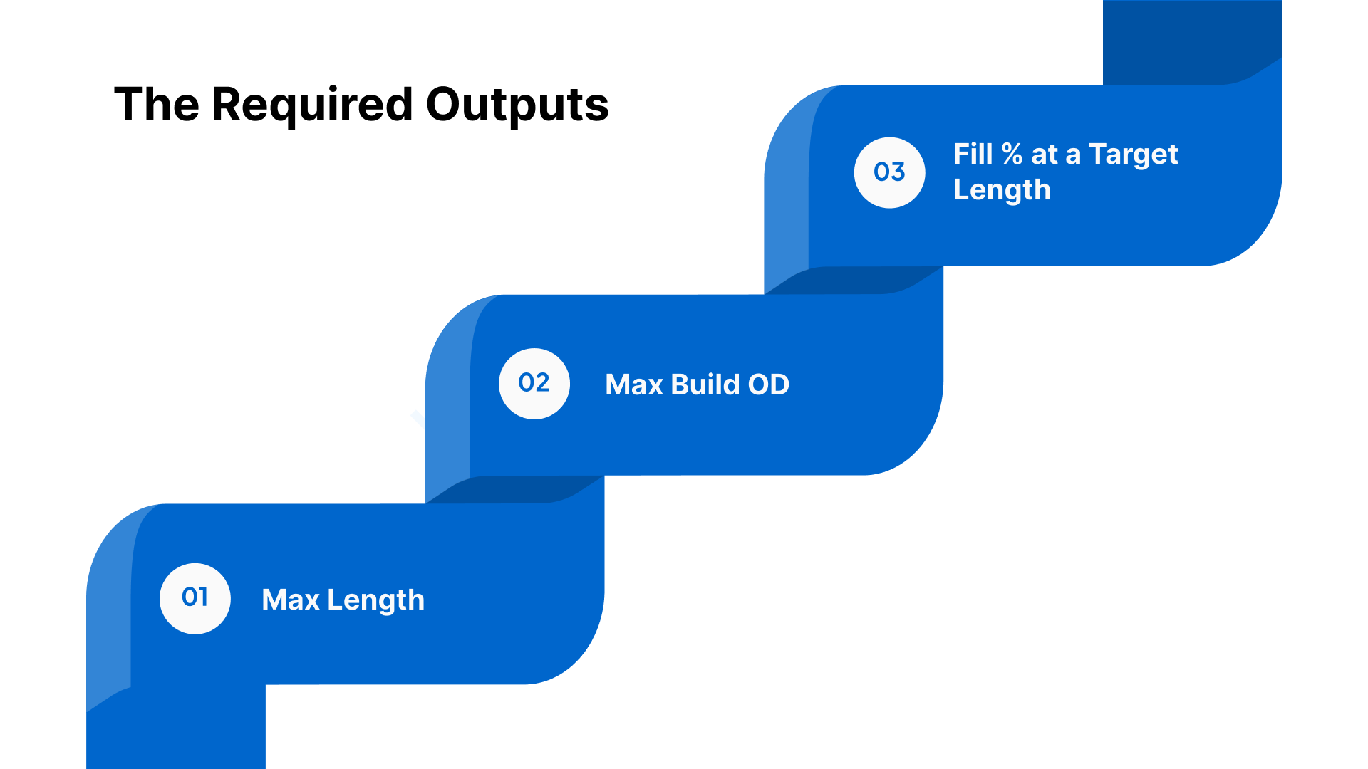
Max Length
This is the only number most teams ask for. It is also the easiest to misuse. The calculator must tie the max length to a declared fill policy (for example, a freeboard rule and wind factor assumptions). If it doesn’t, the “max” number will drift by site.
Max Build OD
This is the output that prevents surprises. It tells you what outer diameter the pack will reach at the stated length or fill target. It also gives ops a way to compare the calculated build to what they see on the floor without guessing.
Fill % at a Target Length
Programs rarely run “maxed out” every time. They run target lengths. The calculator must show the fill percentage at a target length so teams can plan margin, compare lanes, and avoid last-minute changes when a reel is already in the yard.
The Outputs That Add Real Operational Value
These are not mandatory, but they reduce exceptions and email threads. Include them if the calculator can do it cleanly.
Margin-to-Flange (Freeboard) at Target Length
Show how much clearance remains to the flange at the target length. This is one of the fastest ways to avoid fit failures.
Capacity at Standard Fill Targets (Example: 85% and 90%)
Most programs end up standardizing a fill band. This output lets procurement, planning, and ops speak the same language without rerunning calculations for every decision.
Layers/Turns Estimate
This is useful for planning and sanity checks. It should never be positioned as an acceptance metric. It varies with real winding behavior.
Every Output Must Carry Its Own “Header”
If your output can be copied into an RFQ, a spec packet, or a receiving screen without losing context, you have the right format. If it can’t, it will be misused.
Your calculator output should always show:
Units for every value (in/mm for dimensions; ft/m for length)
OD basis label (example: “cable OD = nominal jacket OD” or “OD = measured average”)
Assumption set identifier (example: “Program Standard v3”)
Revision date + owner (so disputes have a single source of truth)
This format allows procurement, receiving, and operations to use the output directly in RFQs/POs and acceptance workflows without rework.
One Rule You State Here, Then Enforce Later
Usable capacity is not valid if it violates rating or handling constraints.
If the output exceeds what the reel can safely carry, lift, restrain, or run, the number is not usable.
These outputs only hold when every site captures the same minimum inputs the same way, with no “interpretation” on dimensions or OD basis.
The Minimum Inputs To Measure And Lock Before You Calculate
A capacity calculator only stays consistent across sites when the same minimum inputs are measured the same way and recorded in a single format. If any one of these inputs is “interpreted,” the output becomes non-comparable across plants, suppliers, and lanes.
The Minimum Input Set
Reel Geometry
Flange OD (F): Record the true outer flange diameter. This is the envelope input that defines the maximum possible build OD boundary.
Drum OD (D): Record the drum outside diameter at the winding surface. This is the starting diameter for build calculations.
Usable Traverse (T): Record the flange-to-flange usable winding width. This must reflect what is actually available for the product, not the nominal traverse.
Cable OD Value
Record the cable OD value used in the calculation and label the basis (example: nominal jacket OD or measured average OD).
Use one OD basis label consistently across the program so outputs remain comparable.
Units
Set one unit standard for the program (dimensions and length).
Convert inputs to the program standard at entry, before running any calculation, so teams do not mix units across sites.
How To Measure Each Input So Sites Don’t Drift
Flange OD (F)
Measure across the flange OD at a consistent reference location.
If the flange shows damage or deformation, capture the measured value and flag the condition for review rather than “correcting” the number in the field.
Drum OD (D)
Measure at the winding surface, not at hubs, collars, or reinforcement features that are not part of the pack geometry.
If there is wear, buildup, or damage, record the measured value and note the condition so the result can be reviewed if it conflicts with field behavior.
Usable Traverse (T)
Measure the usable winding width between flanges and exclude any areas that are not available for product due to fixed obstructions, unusable geometry, or features that reduce the effective winding space.
Record usable traverse as a single number, with a short note only when something reduces it materially (for example, “guard ring reduces usable width”).
The Input Record Format To Lock Program Repeatability
A program-ready calculator input record should be captured in one repeatable line item so it can be reused, audited, and compared.
Include, at minimum:
Reel ID or size family identifier (how your program references the reel)
F, D, usable T (with units)
Cable OD value + OD basis label
Input source (measured, supplier drawing, verified chart)
Revision owner + date (who can change the stored inputs)
This input record is the control point that prevents capacity from turning into site-specific judgment.
Once the inputs are locked, the capacity result still changes based on program assumptions, usable traverse policy, clearance/freeboard, wind factor, and OD basis rules, which must be set explicitly before the calculation can be trusted across sites.
The Assumptions That Change Capacity Enough To Create Bad Calls
Once inputs are consistent, disagreements usually come from assumptions. Two teams can use the same flange OD, drum OD, and traverse and still land on different capacity numbers because they used different clearance rules, different OD bases, or different packing behavior assumptions. In a multi-site program, these assumptions need program-default rules.
Capacity Assumptions That Move The Number
Assumption | What It Changes | Program Default Rule | Failure If Ignored | Where To Document |
|---|---|---|---|---|
Clearance / Freeboard | Reduces usable build OD and effective length | Define a standard freeboard margin to the flange for the program; allow exceptions only through a named approver | “Full on paper” reels that contact flanges, create handling damage, or drive field exceptions | Program capacity standard (assumption set ID) + lane SOP |
Wind / Packing Factor | Changes the effective volume per unit length | Set a default approach by product family (tight-wound vs compliant/irregular pack); require an assumption label on every output | Chronic overfill/underfill, inconsistent yields by plant, disputes between charts and reality | Program capacity standard + product family appendix |
Cable OD Basis | Changes in length per volume materially | Specify the OD basis for planning vs ordering (example: nominal for planning; max/controlled OD for risk-controlled commitments) | Procurement buys on one basis; operations loads to another; repeated “capacity miss” disputes | Program capacity standard + RFQ/PO language |
Usable Traverse Definition | Controls the winding width actually available | Define what traverse excludes (non-usable edge zones, fixed obstructions); assign an owner for maintaining that definition by reel family | Teams use nominal traverse; real winding space is smaller; unplanned spillover and repack | Reel family master record + drawing notes |
Units Standard | Prevents silent conversion errors | One program unit standard; conversion at data entry only; no mixed-unit calculations | Wrong capacity decisions that are hard to detect and replicate | Calculator UI + program standard |
The Program-Default Rules To Set
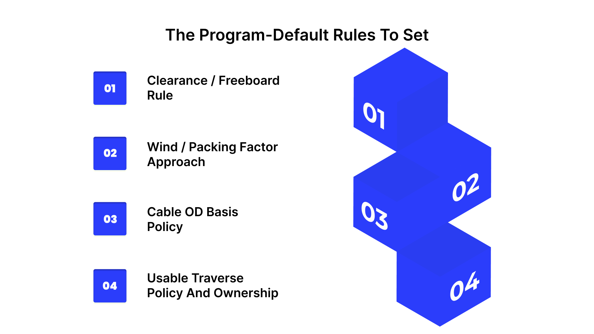
Clearance / Freeboard Rule
Capacity must reflect how the reel is allowed to be loaded in your operation, not the maximum theoretical fill to the flange. Set a program freeboard rule that defines the minimum margin you keep between the pack and the flange.
Default rule: One standard freeboard margin for the program, applied every time.
Exceptions: Allowed only through a defined approver and recorded as a different assumption set ID (so the output is traceable).
Wind / Packing Factor Approach
Your program needs a default approach that reflects product family behavior rather than site judgment.
Default rule: Define wind/packing factor approach by product family, using labeled categories.
Consistency requirement: The assumption label must travel with the output, so different plants are not comparing different pack behavior implicitly.
Cable OD Basis Policy
OD basis selection can swing capacity enough to change reel selection and purchase decisions. Separate planning from commitments.
Default rule: Define which OD basis is used for planning versus ordering/commitment decisions.
Control point: Require the OD basis label on every output so procurement, engineering, and operations are using the same risk posture.
Usable Traverse Policy And Ownership
Usable traverse is not always the nominal traverse. Your program must define what is excluded and who maintains that definition.
Default rule: Define exclusions consistently (non-usable edge zones, known interference areas, and any fixed geometry that prevents winding).
Ownership: Assign a single owner to maintain usable traverse definitions by reel family so “usable width” does not drift by site.
Once assumptions are locked, you still need a fast way to validate outputs before the wrong reel is ordered, shipped, or staged for a job.
How To Validate A Capacity Result Before It Causes Exceptions
A capacity result becomes an exception when it is treated as “the answer” instead of an output that must clear three quick gates.
Run this validation before the release event that commits cost or schedule, RFQ/PO issue, supplier ship authorization, or yard staging for a job. It catches the common failure modes: wrong units, wrong assumptions applied implicitly, and outputs that violate real constraints.
The Three Sanity Checks
1) Units Check
This is the fastest way to catch silent errors that look “reasonable” until the reel shows up.
Confirm one unit system end-to-end for dimensions and length (no mixed inch/mm entries).
Confirm the cable OD basis shown on the output matches the program assumption set used for that decision (planning vs ordering).
Confirm the calculator output prints units next to every value.
Pass condition: No mixed units, OD basis is explicit, and the output is interpretable without context.
2) Geometry Bounds Check
This confirms the result is physically plausible for the reel geometry and the program’s clearance rules.
Check that max build OD respects the clearance/freeboard rule (margin-to-flange is non-negative at the stated target).
Check that the result is feasible given a usable traverse.
Use a quick plausibility screen: if the output implies a build that is effectively at-flange or depends on “perfect pack,” treat it as high risk.
Pass condition: Build OD stays inside the usable envelope under the declared clearance rule, and the traverse assumption is the program-defined usable traverse.
3) Constraint Check
This prevents “capacity” from overriding the limits that actually govern whether the reel can be deployed safely and repeatedly.
Confirm the result does not exceed the reel’s rated load for the intended use class.
Confirm the result is compatible with the handling method limits that apply in your network (lift/secure/transport constraints).
Confirm the output does not create a downstream requirement that the operation cannot meet (for example, a loading condition that consistently forces exception handling at the yard or on the line).
Pass condition: The calculated load condition is inside rating and handling limits, and the result is deployable without exceptions.
What To Do When A Calculator Result Conflicts With A Supplier Chart
Chart mismatches are usually an assumption mismatch. Treat them as a reconciliation task.
Identify which assumption differs first: OD basis, freeboard/clearance, usable traverse, or packing behavior.
Align the comparison to the program assumption set you intend to enforce.
Document the delta as a short note attached to the capacity record (example: “Chart assumes nominal OD and full traverse; program uses usable traverse and clearance rule.”).
Decision rule: If the same mismatch repeats across sites or product families, it is not a one-off. It signals that the program assumption set or input capture method is not being applied consistently.
Escalation Triggers
Define escalation as decision points only. The goal is to stop recurring exceptions from being normalized.
Repeat calculator-to-chart mismatches for the same reel family or product family.
Repeated receiving exceptions tied to “capacity” outcomes (overfill, handling conflicts, or repeated rework).
Field behavior that conflicts with the computed build (consistent instability, unexpected pack behavior, or frequent interventions).
Validation only reduces exceptions when results are stored, versioned, and reused consistently across sites and procurement.
Store validated outputs as governed capacity records.
How To Package And Store Capacity Outputs So Sites Stop Re-Interpreting Them
Validation prevents bad reels from slipping into the system. Packaging prevents the same debate from happening again next week.
The objective is a single capacity reference that procurement can cite in RFQs/POs and operations can use at planning, receiving, and staging, without recalculating or reinterpreting.
Convert “A Calculation” Into A Controlled Capacity Record
Treat capacity like a controlled spec line item, instead of a worksheet output. The record needs to be usable without the person who ran the math.
A program-ready capacity record should include:
Capacity Record ID: A unique identifier that can be referenced in RFQs, POs, receiving notes, and internal planning.
Reel Family + Application Context: The reel family this applies to and the specific use context it supports (for example: product family or lane type), so the wrong record is not applied to a different scenario.
Inputs + Assumption Set Reference: A compact reference to the stored input record and the named assumption set version used for the decision.
Outputs: Presented as a single block that can be pasted into a spec packet without reformatting.
Governance Header: Revision date, revision owner, and a short change note describing what changed and why.
The goal is to prevent uncontrolled re-creation of capacity numbers.
Use A Naming Convention That Stops “Catalog Label Drift.”
Most multi-site confusion comes from teams using different shorthand for the same reel, or the same shorthand for different reels.
Define a naming rule that is based on program identifiers rather than vendor marketing names:
Tie the record name to the reel family identifier your program uses.
Add a clear differentiator when a reel family has multiple valid capacity records (for example: by product family or lane context).
Avoid names that only reflect a supplier’s catalog description unless you are also mapping them to the program’s reel family identifier.
Outcome: procurement, suppliers, and sites reference the same record by the same name.
Establish Change Control That Matches Real Failure Modes
Capacity standards drift when edits happen quietly. You need lightweight governance, instead of a heavyweight process.
Set three rules:
Who can issue a new version: Name the function or role that owns the capacity library and can publish changes.
What forces a version bump: Any change that would alter ordering decisions, supplier commitments, or deployment outcomes must trigger a new version.
What requires explicit approval: If a change modifies the program’s risk posture (for example, tighter or looser loading rules), require approval from the program owner group rather than leaving it to a single site.
Keep the output of change control simple: one revised record with a clear reason for change.
Decide Where The Source Of Truth Lives, Then Enforce It
Pick one location that your procurement and operations teams already use. Then make it the only reference that matters.
Practical options:
Spec packet library: Works well when suppliers need to quote and comply against a defined capacity basis.
Shared capacity library: Works well for multi-site programs that need versioning and access discipline.
ERP reference field: Works well when you want buyers to pull the correct record at the point of purchase.
Enforcement rule: the source of truth must be reachable from the purchase workflow and from the receiving workflow. If teams cannot access it at the decision point, they will recreate it.
Define How Each Team Uses The Record
This prevents the record from becoming the information that no one trusts.
Procurement: References the capacity record ID/version in RFQs and POs to prevent supplier chart substitution.
Operations / Planning: Uses the stored capacity outputs to select reels and plan loads without rerunning calculations.
Receiving / Yard: Uses the record as the reference point for acceptance decisions and exception coding, rather than relying on verbal guidance.
Close The Loop After Exceptions
When exceptions occur, the fix should update the system.
If the issue is a one-off data problem, correct the specific record and document the reason.
If the issue repeats across sites, treat it as a program standard problem and update the assumption set or record definition through formal versioning.
If exceptions persist even when capacity records are controlled and reused, the limiting factor is usually reel condition and verification.
Stabilize Capacity Decisions With NARCo - New American Reel Co LLC
If capacity records are controlled, assumptions are locked, and validation is still passing, recurring exceptions usually point to reel condition and interface integrity rather than calculation logic.
NARCo restores steel reels to repeatable service condition through reconditioning and targeted repairs, reducing field instability within reel families that are treated as equivalent in program planning.
What NARCo Can Do That Supports Repeatable Capacity Outcomes
Standard reconditioning services
Straightening and pressing work for flanges
Repairs for damaged rims
Blasting and painting
Stenciling (logo/name and/or tare weight)
Dynamic balancing
Custom repair services
Repairing or replacing drive pin holes
Repairing or replacing arbor tubes
Changing the arbor hole size
Welding, fabricating, and machining as needed
Coverage range: Reel sizes ranging from 3” to 96” (75mm to 2400mm).
How This Helps A Multi-Site Program Reduce Exceptions
When recurring issues are driven by reel variability, the practical program benefit is fewer uncontrolled differences between reels that are treated as the same family. Reconditioning and repair can:
Restore functional geometry so capacity assumptions remain valid in practice.
Reduce interface-driven run instability by correcting wear or damage in engagement features (where applicable).
Support cleaner re-entry discipline through consistent finish/marking and tare labeling (when used as part of program controls).
Decision-Grade Outputs To Ask For
To keep this aligned with procurement and operations, the objective is to translate corrective action into updates that your capacity library can actually use. A technical review is most effective when it results in:
A clear repair scope aligned to the failure mode (flange/rim/drive features/arbor features).
A disposition recommendation at the reel-family level (return to service after reconditioning vs retire/replace).
A practical update path back into your capacity record system (which reel families need reconditioning vs replacement to stop recurring exceptions).
Request a short technical review from NARCo focused on repair scope and stabilization thresholds for your highest-volume reel families, so recurring exceptions are addressed through controlled reconditioning or retire/replace decisions instead of repeated local workarounds.
Conclusion
A reel capacity method becomes reliable when it is treated as a program standard with clear inputs, declared assumptions, and controlled records that travel with purchasing and receiving.
When problems continue after standardization, the limiting variable is often the reel itself. Geometry drift, wear at engagement features, and inconsistent conditions across a “single” reel family can invalidate otherwise disciplined calculations.
In those cases, the fastest path to stability is to restore repeatable reel condition and tighten what qualifies for re-entry, rather than refining the spreadsheet.
Use the calculator and capacity library to set a consistent decision basis. Use verification and corrective action to keep reel families inside the condition envelope that the basis assumes. This is how capacity planning stays aligned with real handling and run behavior across sites.
FAQs
How do you calculate reel capacity for cable?
Use flange OD, drum OD, usable traverse, the cable OD basis, and a defined packing assumption. Keep the assumption set fixed so results remain comparable across plants and suppliers.
What measurements do I need for a reel capacity calculator?
Flange OD, drum OD at the winding surface, usable traverse/width, and the cable OD value used in the calculation. Record all inputs in the program unit standard.
Why doesn’t my calculated capacity match the manufacturer's chart?
The underlying assumptions usually differ in terms of definition, clearance/freeboard, packing behavior, or OD basis. Align to one assumption set before treating the delta as a data issue.
What is a wind factor in reel capacity calculations?
A packing allowance that accounts for real winding and voids versus an ideal pack. It prevents overstated capacity that later shows up as overfill, flange contact, or rework.
How much clearance should I leave on a reel when calculating capacity?
Set a program default based on the handling and damage thresholds you can enforce, then apply it consistently. Any deviation should be treated as an exception with documented approval.
Can a reel fit the length but still be wrong?
Yes. Rating limits, handling constraints, and interface compatibility can make a “volume-fit” result unusable even when the calculated length appears feasible.