This guide covers the tools required, three practical verification methods (from shop-grade to field screening), how to read the results, and what corrective action to take when a reel fails spec.
Key Takeaways
- Static checks alone cannot detect couple (end-to-end) unbalance — the reel must be spinning for a valid test
- Three methods exist: two-plane dynamic balancing machine, in-situ vibration analysis, and static balance (screen only)
- Unbalance readings use oz-in (imperial) or g-mm (metric) units
- Tolerance limits come from reel weight, operating speed, and the ISO 1940-1 G-grade for your application
- Out-of-spec readings require weight correction or professional reconditioning — not just re-inspection
- Always confirm lockout/tagout on the drive and clear personnel from the rotational plane before spinning a reel on any balancing rig
What You Need to Verify Dynamic Reel Balance
Method choice depends on the reel's size, operating speed, and what equipment is available on-site. The wrong choice produces misleading readings, wasted machine runs, or both — so confirming fit before setup matters.
Tools Required
| Tool | Purpose |
|---|---|
| Dynamic balancing machine (soft- or hard-bearing) | Primary measurement of unbalance magnitude and angle |
| Vibration sensor / accelerometer with data readout | In-situ bearing housing measurement |
| Dial indicator | Preliminary runout check before mounting |
| Calibrated tachometer or speed sensor | Confirm actual spin RPM |
| Correction weights (lead slugs or steel washers) | Flange adjustments after measurement |
Soft-bearing machines use freely moving supports and maintain sensitivity across their speed range; hard-bearing machines use rigid supports and need stiffer foundations, but offer permanent calibration and faster cycle times for high-volume work.
For large wire reels, confirming the machine's rated weight capacity and journal diameter range before mounting is not optional. Narco's reconditioning work covers 3" to 96" (75 mm to 2,400 mm) diameter, so machine fit varies considerably by job.
Preconditions and Setup
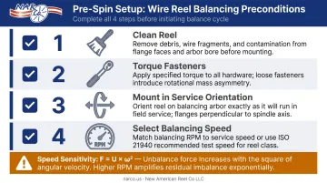
Before any spin, confirm these conditions:
- Clean the reel completely — wire tails, corrosion buildup, and surface debris shift the center of mass and produce false readings
- Torque all flange bolts and hub fasteners to spec — loose hardware introduces variable mass during spin
- Mount in service orientation — journals must seat fully in the balancing machine's bearing cradles, spin axis horizontal, with no axial play
- Select balancing speed carefully — target 50–100% of the reel's actual operating RPM, always above the machine's minimum threshold. Unbalance force follows F = U × ω², meaning testing at too low an RPM underestimates centrifugal force by the square of the speed ratio
Methods to Verify Dynamic Reel Balance
No single method fits every situation. A post-reconditioning acceptance test demands shop-grade precision; a condition monitoring check on the production floor has different requirements.
Method 1: Two-Plane Dynamic Balancing Machine
This is the preferred method for acceptance testing wire reels. The reel spins on a balancer that simultaneously measures centrifugal force at two bearing planes, resolving both static (force) unbalance and couple (moment) unbalance independently for each correction plane.
Step-by-step process:
- Mount the reel on the machine's bearing supports, journals fully seated, reel rotating freely with no axial play. Zero the readout for the unloaded fixture.
- Spin to the target balancing speed; hold steady for at least 30 seconds. Record unbalance magnitude (oz-in or g-mm) and angular position (degrees) for Plane 1 (left flange) and Plane 2 (right flange) separately.
- Add correction weight at the indicated angle on each flange — or remove material by drilling where the reel design permits. Re-spin to confirm residual unbalance falls within the acceptable tolerance.
Per ISO 1940-1, permissible residual unbalance is calculated as: Uper (oz-in) = 6.015 × G × W / N, where G is the balance quality grade, W is rotor weight in lb, and N is maximum service RPM.
- Best for: Fully resolving couple unbalance in reels with significant face length; standard for acceptance testing after repair or new fabrication
- Limitation: Requires a rated balancing machine and trained operator — not a field-deployable tool
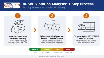
Method 2: In-Situ Vibration Analysis During Controlled Spin
When shop-grade balancing equipment isn't available on the floor, in-situ vibration analysis is the practical alternative. This method measures bearing housing vibration while the reel spins on its actual machine or a test stand — most useful as a field verification check after a reel returns from balancing, or as part of ongoing condition monitoring.
Step-by-step process:
- Mount the accelerometer firmly on the bearing housing in the radial direction. Note the exact location — consistency between readings matters.
- Spin to normal operating speed; allow 30 seconds to stabilize. Record overall vibration level and the 1× RPM amplitude in horizontal and vertical directions at each bearing.
- Compare against ISO 20816-3 zone boundaries or your facility baseline. A dominant 1× spike at running speed is the primary unbalance indicator.
Phase data adds diagnostic value: static unbalance produces matching phase angles at both bearings; couple unbalance produces phase angles ~180° apart.
ISO 20816-3 velocity severity zones (broadband RMS, mm/s):
| Zone | Meaning | Group 2 boundary |
|---|---|---|
| A/B | New machine → acceptable | 1.4 mm/s |
| B/C | Acceptable → limited operation | 2.8 mm/s |
| C/D | Limited → damage risk | 4.5 mm/s |
- Best for: Trending reel condition over time without removing it from the machine
- Limitation: Does not produce oz-in figures or angular correction positions — cannot guide weight correction on its own
Method 3: Static Balance Check (Preliminary Screen Only)
The reel rests on frictionless knife-edge rails or a roller stand; gravity rotates the heavy side down, revealing static (single-plane) unbalance.
Critical limitation: Static balance cannot detect couple unbalance, where equal heavy spots at opposite ends offset each other gravitationally but still generate oscillating forces at speed. Treat this as a screening step, never a pass/fail dynamic balance test.
Step-by-step process:
- Place reel journals on level rails; allow it to settle naturally. Mark the top (light side) with chalk.
- Rotate the reel 90° and release. If it returns to the same bottom-heavy position, static unbalance is confirmed. Repeat twice for consistency.
- Estimate magnitude by adding small trial weights to the light side until the reel no longer rotates when released. Document findings, then proceed to a two-plane dynamic check.
- Best for: Quick initial screening with no powered equipment required
- Limitation: A reel that passes this check may still carry significant couple unbalance — always follow with a two-plane dynamic check before returning to service
How to Interpret the Results
Misreading balance data is a common, costly error. Here is what each reading category means and what action it triggers:
Normal / Acceptable Residual unbalance falls within the tolerance for the reel's operating speed and weight. For general industrial rotating equipment, G6.3 is a common starting point under ISO 1940-1 — for a 50 kg reel at 300 RPM, that works out to roughly 13.9 oz-in (10,026 g-mm). Higher-precision applications may require G2.5 or tighter. Confirm the applicable grade with the reel manufacturer or your reconditioning specialist. → Document readings and return to service.
Minor Issues Residual unbalance slightly exceeds target tolerance — say, within 1.5× the specified limit — but no audible noise or visible wobble is present during spin. → Flag for correction at the next scheduled maintenance interval. Avoid operating above standard speed until corrected. Increase monitoring frequency.
Out-of-Spec Unbalance significantly exceeds the allowable limit, or 1× RPM vibration at the bearing housing exceeds ISO zone B thresholds. Observable signs include:
- Audible bearing rumble during spin
- Visible end-to-end reel wobble
- Phase angle reversal between measurement planes (indicating a dominant couple component)
→ Remove from service immediately. Minor flange weight corrections can be attempted in-house if a rated two-plane balancing machine and trained operator are available.
Reels with bent flanges, weld distortion, or large unbalance magnitudes require a qualified reconditioning shop. Narco has handled reel assessment, structural repair, weight correction, and post-repair verification for wire and cable manufacturers across the US since 1999 — contact them for reels that exceed in-house correction capability.
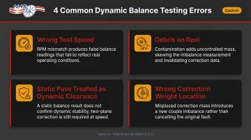
Common Errors When Checking Dynamic Reel Balance
Each of these errors is specific to the wire reel context. Left uncorrected, they produce false readings, missed defects, and — in high-speed service — bearing failures that could have been caught at the balancing stage:
Testing at the wrong speed: Balancing well below operating RPM underestimates centrifugal force (F = U × ω²) and misses couple unbalance components that only appear at higher speeds. Document the balancing speed so future checks run at the same RPM.
Debris or wire remnants left on the reel: A short wire tail or flange corrosion patch adds enough eccentric mass to generate a false reading. Clean the reel thoroughly before mounting.
Treating a static pass as dynamic clearance: A reel that passes on balance rails is not cleared for high-speed service. Couple unbalance is invisible to a static test and can still cause destructive bearing loading. Follow any static screen with a two-plane check for reels operating above low RPM thresholds.
Placing correction weight at the wrong location: Weight must go on the flange faces or head locations designated for that reel model. Attaching weight at an arbitrary point on the barrel shifts the couple arm and can worsen couple unbalance even while reducing the static component.
Safety and Best Practices
Before Mounting Any Reel on a Spin Rig
Apply lockout/tagout per OSHA 29 CFR 1910.147 and verify zero energy state. Confirm the reel's journal diameter is within the machine's rated range and that bearing cradle stops are in place.
PPE and Personnel Safety
- Wear safety glasses per 29 CFR 1910.133
- Stand clear of the reel's rotational plane during spin-up
- No loose clothing, gloves, or jewelry near the rotating reel
- Barricade the area within the reel's radius
- Clear all non-essential personnel before engaging the drive
Keep Surfaces Clean
Foreign material under the journal introduces measurement error and can cause the reel to walk off the support.
Conclusion
Accurate dynamic reel balance verification depends on matching your measurement method to the reel's geometry, operating speed, and the tolerance standard you're working against. A two-plane balancing machine is the only tool that resolves both static and couple unbalance in wire reels with significant face length. In-situ vibration analysis supports field monitoring and trending, but it cannot replace shop measurement for acceptance testing.
When reviewing results, keep these action steps in mind:
- Match balancing speed to actual operating conditions
- Interpret readings against a defined tolerance — ISO 1940-1 G-grade or your OEM spec
- Address minor deviations promptly with in-house weight correction
- Send reels with structural damage or compound balance problems for welding, machining, and professional rebalancing
Narco has provided dynamic balancing alongside reel reconditioning and fabrication services since 1999 — contact the team if a reel comes back out of spec and needs more than a field adjustment.
Frequently Asked Questions
What are the signs of dynamic imbalance?
The primary signs include a dominant vibration at 1× operating RPM measured at the bearing housings, audible rumble or bearing noise during spin, and visible end-to-end wobble at speed. Unlike static imbalance, couple imbalance may not be visible at rest; accelerated bearing wear is typically the first noticed symptom.
What is the difference between static and dynamic balance in a wire reel?
Static balance means the reel's center of mass sits on its rotation axis, detectable at rest by gravity. Dynamic balance additionally requires the principal inertia axis to align with the rotation axis. A reel can pass a static check yet still carry couple unbalance that causes oscillation at speed, making two-plane spinning verification essential above low RPM thresholds.
What is an acceptable unbalance tolerance for a wire reel?
Tolerance depends on reel weight, operating speed, and the applicable grade. Using ISO 1940-1 (Uper = 6.015 × G × W / N), a 110 lb reel at 300 RPM under G6.3 yields roughly 13.9 oz-in permissible residual unbalance; precision applications may require G2.5 or tighter. Confirm the correct grade with your reel manufacturer or reconditioning specialist.
How often should wire reels be checked for dynamic balance?
Check after any repair (welding, machining, flange replacement), after a visible impact or drop event, and as part of scheduled reconditioning cycles. Reels showing an increasing vibration trend during condition monitoring should be pulled for a full dynamic balance check before bearing failure occurs.
Can dynamic reel imbalance be corrected in-house, or is professional service required?
Minor corrections, such as adding small calibrated weights to the flange face, can be done in-house with a rated two-plane balancing machine and a trained operator. Reels with bent flanges, weld distortion, or large unbalance magnitudes require a qualified shop with machining and welding capability to restore structural integrity before rebalancing.
Does wire wound on a reel affect its dynamic balance?
Yes. Wire payout continuously changes the reel's mass distribution during use, so reels are balanced in their empty (or specified loaded) state per the operating profile. Monitoring bearing vibration during operation, not just inspecting the empty reel, is part of a complete balance management program.